目录
多用途XYZ控制平台
- 这是由15级戴植锐同学设计制作的,
- 目前由俞熹 维护

郑重声明
- 没有经过指导的同学请勿擅自操作! 请培训后上岗
- 所有车床工序,请反复模拟后再实践
- 加工过程中可能有飞溅物,注意防护, 千万不要尝试危险的动作,三思而后行!
- 尝试一些新的加工参数时,建议找有经验的人指导!
- 如果触碰了限位开关,请关闭系统再开. 不要反复犯错. 犯错后及时联系管理员进行修正!
使用说明
- GCODE 是数控车床 CNC(Computerized Numerical Control)通用的语言.
- 开机 电源按钮有两个, 绿色是xyz控制电源, 红色是钻头电源,如果不使用钻头请勿开启.
- 连接控制器, 控制器有两根usb线, 请连接上方的一根usb,这根线是连接Arduino CNC的. 请安装标准的Arduino usb驱动程序.
- 通过rs232 通讯可以连接Arduino CNC, 输入 $$ 检查 参数表. - 输入 $H 会初始化机器,重置到默认XYZ位置.
- 输入 $X可以解锁状态. 开始可以控制电机移动.
- 制作刀路图可以用 Autodesk ArtCam (ftp上有) 生成刀路以后, 用奎享微雕(边上机器上有) 导入刀路后制作.但是中间过程很复杂, 请不要自己尝试.

钻头控制M3, M4, M5 Spindle Control
- M3 - start the spindle clockwise at the S speed.
- M4 - start the spindle counterclockwise at the S speed.
- M5 - stop the spindle.
- Sx - set the speed of the spindle to x revolutions per minute (RPM).
- It is OK to use M3 or M4 if the S spindle speed is set to zero. If this is done (or if the speed override switch is enabled and set to zero), the spindle will not start turning. If, later, the spindle speed is set above zero (or the override switch is turned up), the spindle will start turning. It is OK to use M3 or M4 when the spindle is already turning or to use M5 when the spindle is already stopped.
螺旋切割实例说明
- 代码说明:
- XY-plane (G17)
- G2 or G3 <X- Y- Z- I- J- P→
- Z - helix
- I - X offset
- J - Y offset
- P - number of turns
- G0 X0 Y0 初始位置.
- G2 X1 Y1 I1 F10 (clockwise arc in the XY plane) 顺时针移动.
- F10 进10步.

- G17 G2 X10 Y15 R20 Z5
- G17 工作平面选定 XY
- G2 顺时针切割.
- X10 Y15 Z5 最后结束坐标点. 如果Z初始=5 则是平面移动, 否则就是螺旋移动.
- R20 半径大小.
本机支持的G-Codes - Supported G-Codes in v1.1
G0, G1: Linear Motions  直线(快速)移动.
G2, G3: Arc and Helical Motions 圆弧移动
G4: Dwell  停留时间.
G10 L2, G10 L20: Set Work Coordinate Offsets 工具(切换)坐标
G17, G18, G19: Plane Selection 工作平面选择
G20, G21: Units  长度单位.设置.
G28, G30: Go to Pre-Defined Position  快速移动到设定位置
G28.1, G30.1: Set Pre-Defined Position  设置当前位置为设定位置
G38.2: Probing (需要有反馈信号)
G38.3, G38.4, G38.5: Probing (需要有反馈信号)
G40: Cutter Radius Compensation Modes OFF (Only)  刀头补偿
G43.1, G49: Dynamic Tool Length Offsets
G53: Move in Absolute Coordinates  按照机器绝对坐标移动.
G54, G55, G56, G57, G58, G59: Work Coordinate Systems  选择工作坐标表.
G61: Path Control Modes
G80: Motion Mode Cancel  取消当前命令组.
G90, G91: Distance Modes  绝对路径/相对路径 编程模式
G91.1: Arc IJK Distance Modes
G92: Coordinate Offset  工件坐标系设定.
G92.1: Clear Coordinate System Offsets
G93, G94: Feedrate Modes  移动模式选择(G93 多少分钟 进多少步, G94 每分钟进多少步.)
M0, M2, M30: Program Pause and End
M3, M4, M5: Spindle Control  钻头刀具控制
M7* , M8, M9: Coolant Control  冷却液控制.
M56* : Parking Motion Override Control
(*) denotes commands not enabled in config.h by default.
Multipurpose 3D Stage
In this project, we design and build a 3D stage for multiple purposes, such as 3D scanning, 3D printing, engraving, etc. After through discussion and careful verification in SolidWorks, we bought material and built up the stage one time successfully.
By utilizing Grbl for Arduino CNC Board, the spindle of the stage can walk along the designed route under the control of an Arduino Mega Board and a computer. Because Grbl is designed based on G-Code standard, it is easy to use a normal CNC software to send a G-Code sequence which represents the expected route from the computer to the Arduino board. Then, the Grbl program running on the Arduino board interprets the received G-Code and controls a bunch of signals that control three step motor drivers, protection switches, optical grating encoders, spindle switch, etc.
Tech Spec
- Spindle Moving Range: 70cm x 70cm x 50cm
- Screw Pitch of Rod: 5mm
- Step Motor Theoretical Accuracy: 0.78 $\mu m$ (Step motor: 57mm, 200 pulses/r, Step Motor Driver is set to 32-microstep.)
- Optical Grating Encoder: 360 lines/inch (accuracy: 70.56 $\mu m$)
- Practical Accuracy: 0.1mm
- Four axes: one for X, one for Y and two for Z
- At the both ends of each axis, there is a limiting switch to protect the working stage from collision.
- Working stage supports mounting different objects for different purposes.
Grbl Key Parameter
- $\$$100 = $\$$101 = $\$$102 = 1280 ([X,Y,Z] steps/mm)
- $\$$110 = $\$$111 = $\$$112 $\leq$ 1500 ([X,Y,Z] Max rate, mm/min)
- $\$$130 = $\$$131 = 700, $\$$132 = 600 ([X,Y,Z] Max travel, mm)
Send command '$\$\$$' to check Grbl setting.
$0=10
$1=25
$2=0
$3=5
$4=0
$5=0
$6=0
$10=1
$11=0.010
$12=0.002
$13=0
$20=0
$21=1
$22=1
$23=0
$24=25.000
$25=500.000
$26=250
$27=5.000
$30=1000
$31=0
$32=0
$100=1280.000
$101=1280.000
$102=1280.000
$110=2560.000
$111=2560.000
$112=2560.000
$120=10.000
$121=10.000
$122=10.000
$130=600.000
$131=600.000
$132=600.000
Grbl Command
Blueprint
- Rendered by SolidWorks

SolidWorks Files for this project, please open system3.SLDASM after unarchiving the archive.
Circuit Design

The Arduino Uno board runs the Grbl program and the Mega board is responsible for decoding the signals of three optical gating encoders to provide more accurate position information.
Softwares
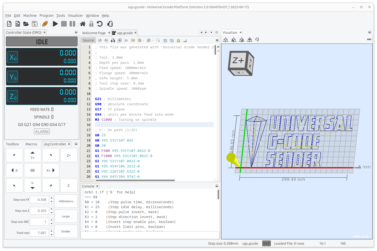
UniversalGCodeSender for Windows and macOS
UniversalGCodeSender is based on java. So, it can run on nearly all platforms supporting java. In the archive above, we provide a bat file for launching UniversalGCodeSender in Windows and a packed App for macOS.
Demonstrations
The Whole Machine
The Control Box and Buttons on it


Circuits in the Box

The Power Supply
The Limit Switch

The Driller for Graving

Graving Effect
