Fiber Raman system for Diamond Anviel Cell
Background: what is Diamond Anviel Cell
Recently, it has been reported that the hydrogen sulfide undergoes a superconducting transition under ultrahigh pressure around 150GPa at a record high critical temperature of 203K.(News,paper) This exciting discovery is just another demonstration that novel phases probably exist under ultrahigh pressure.
The standard method to produce extreme high pressure like this is to use a Diamond anvil cell. (figure 1) This technique was developed during the first half of the 20th century, and has not been changed much because diamond is still the hardest material in nature. Here is a review article for DAC technique.
Figure1:Schematic diagram for DAC(From Wikipedia)
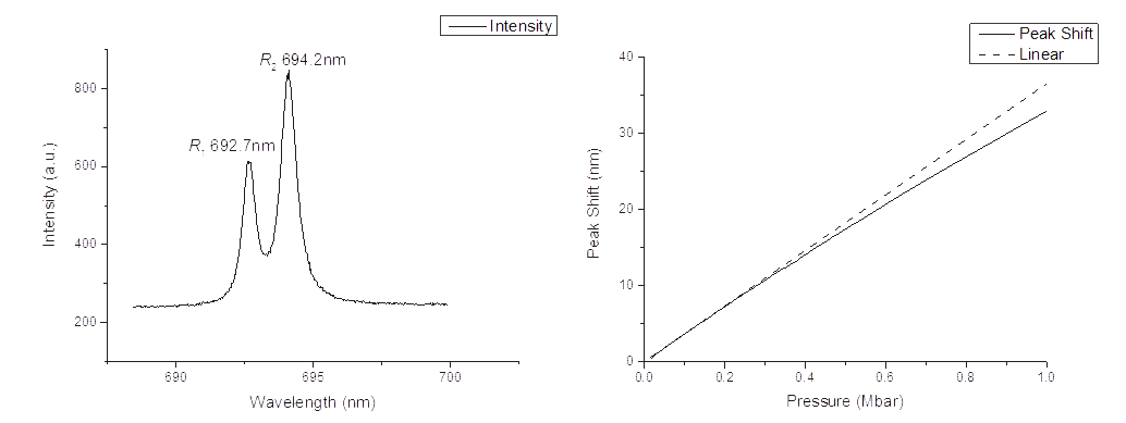
The R fluorescence peaks of ruby would shift under high pressure, which could be used to calibrate the pressure in the diamond anvil cell. The rule of shifting was revealed by the pioneers in high pressure physics. A tiny ruby ball is placed near the sample as a probe, and the silicone oil confined in the gasket would ensure the pressure on the sample and the ruby to be the same. Here is an online calculator that could convert the peakshift to the pressure.
Figure2:Left:Ruby fluorescence spectrum at 1 atm excited by 532nm laser; Right:peak shift in nm verses pressure in mega bar(reproduced from Mao et al. Science 200,1145 ,1978.)
Combine DAC with cryogenic device
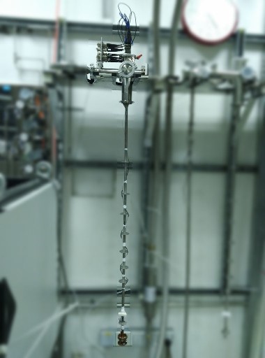
Combining the DAC with the cryogenic devices in the laboratory, we could control the temperature degree of freedom in phase changing. First, a probe would be needed to place the DAC into the center of the refrigerator. Then, wires and fibers should be asigned to guide the signal in and out. To avoid the formation of frost, the device is filled with helium as protecting gas when working. So all the wires and fibers should pass a feedthrough to avoid leaking. Our lab expertizes in transport measurement, so arranging wires for the probe is routine work for us. However, assembling a fiber system has never been tried before.
Figure3: Left:Helium-4 refrigerator in our lab; Right: sample probe
Based on my understanding of Raman system, I designed it as follows. Currently we are only interested in the photoluminescence signal, so no fliters are needed to block the Rayleigh scattering light.
Figure4:Schematic diagram for fiber Raman system
The fiber laser is from Changchun New industries, and the spectrumeter is from ocean optics.
The feedthrough is from fiberguide fiberguide industries, here is the blueprint of the feedthrough.
The lens is ordered to focus the laser on the diamond anvil, I also used Solidworks to design a lens holder for it. Here is the blue print of my design.
All the fibers we used are 105μm/125μm multimode optical fiber which is prevail in fiber optics. Despict the SMA905 connections at the laser source and the spectrumeter, all other connections are through FC.
Prototype verifying
We have a standard Raman system in our lab with the 532nm laser, backscattering microscope and the spectrometer. What I did was to utilize the exist fiber Raman system to test new fiber components one by one.
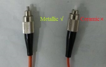
My testing began with a fiber with one lens on each side, I first removed the objective lens of the microscope and replaced it with one of the fiber lens, the laser beam could thus shed out and focus on the other side. The first problem was the fake signal: I could detect the ruby PL peaks without ruby sample! Soon, I managed to find that the problem was in the ceramic terminals. This material has the similar components with ruby so it will introduce fake signal. After I used the metallic ternimals the fake signal disappeaed.
Figure3:metalic and ceramic terminals
The sample I used was first a microscope slide with many micro ruby balls on it. After succeeded, I tried to detect the signal form a single ruby ball. With the help of a 3D motion stage, I managed to do it again. Then I tried the real DAC with a single ruby inside. I also designed a lens holder with the solid works to establish easy and robus connection between fiber lens and DAC. Here is the blus print.
Also since the space in the cryogenic device is limited, I optimized the arrangement of the fibers and wires so that it could be more compact. The first generation probe for DAC was based on the previous design which only considered the wires but but not the fibers and lens, the second generation probe integrated the lens holder on it. Here is the blue print.
Figure4: Prototype verifying
Figure5:I am testing the fiber Raman system


